
Overview
In this project, the goal was to dive into the world of RC car building, using my prior knowledge of 3D printing and motor control. The project served as a hands-on introduction to building an RC car and understanding the key elements that go into its design.
I aimed to create a fully functional RC car, featuring a custom-designed chassis, BLDC (Brushless DC) motors, and a carefully selected gear ratio to optimize both speed and torque. Additionally, the project allowed me to expand my skills in using CAD software for design, as well as improve my understanding of motor control and RC vehicle mechanics.
Main Body Design
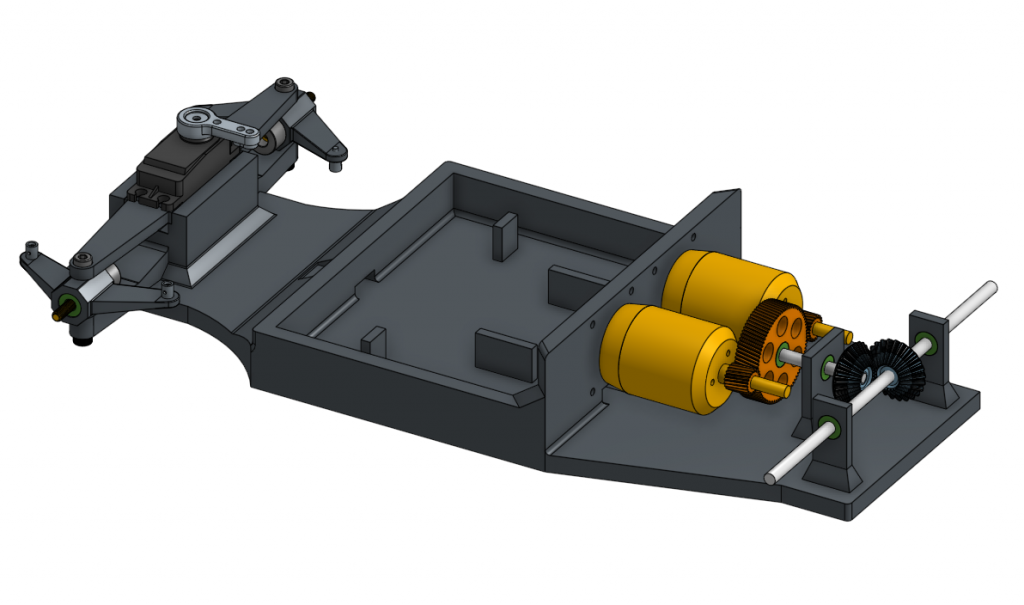
To maintain the simplicity of this design, I didn’t want to use a modular design as that would take longer to design so I made the car out of 1 long piece. This main body can be broken up into 3 sections: the steering section, the middle/component section, and the rear section.
- Steering Section:
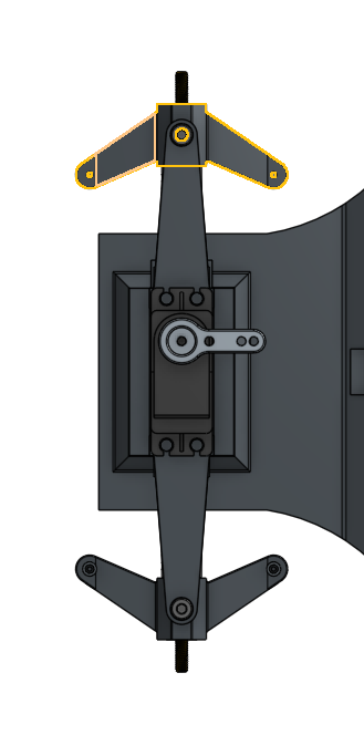
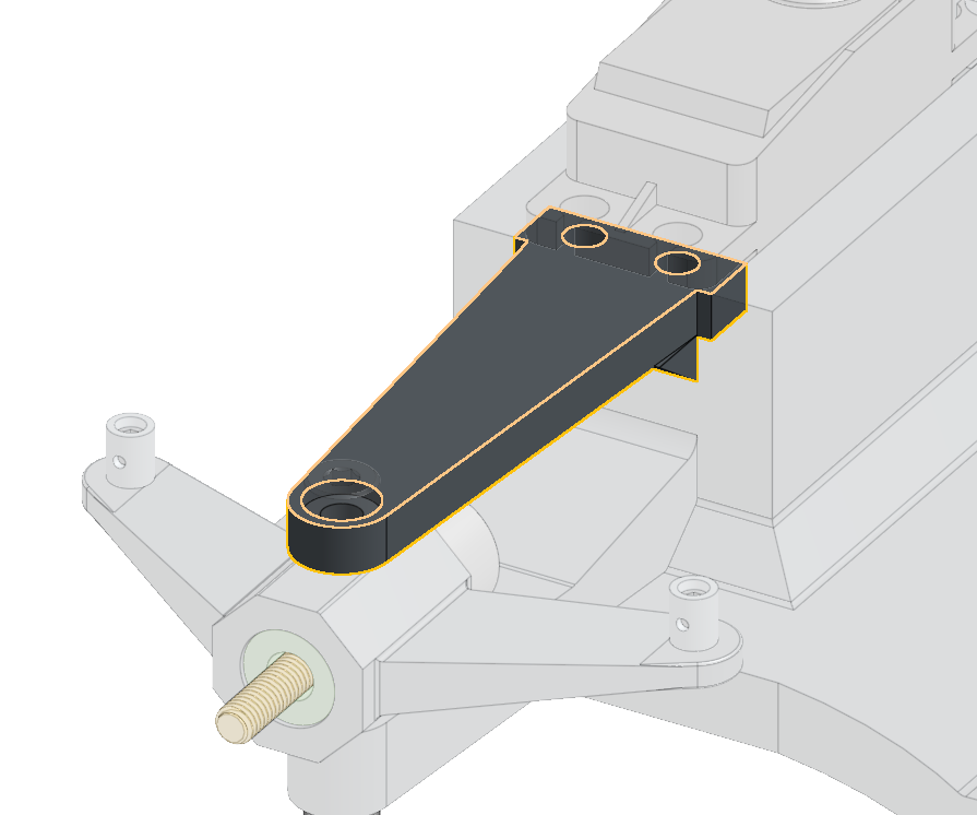
- This section uses a high-torque servo to control the steering; the servo connects to a pushrod linkage system which is what rotates the wheels
- Both front wheels connect to a Steering Knuckle (yellow outlined part in image) which is a free-rotating piece that attaches to the car and the wheel and is rotated via the pushrod linkage system
- Component Section
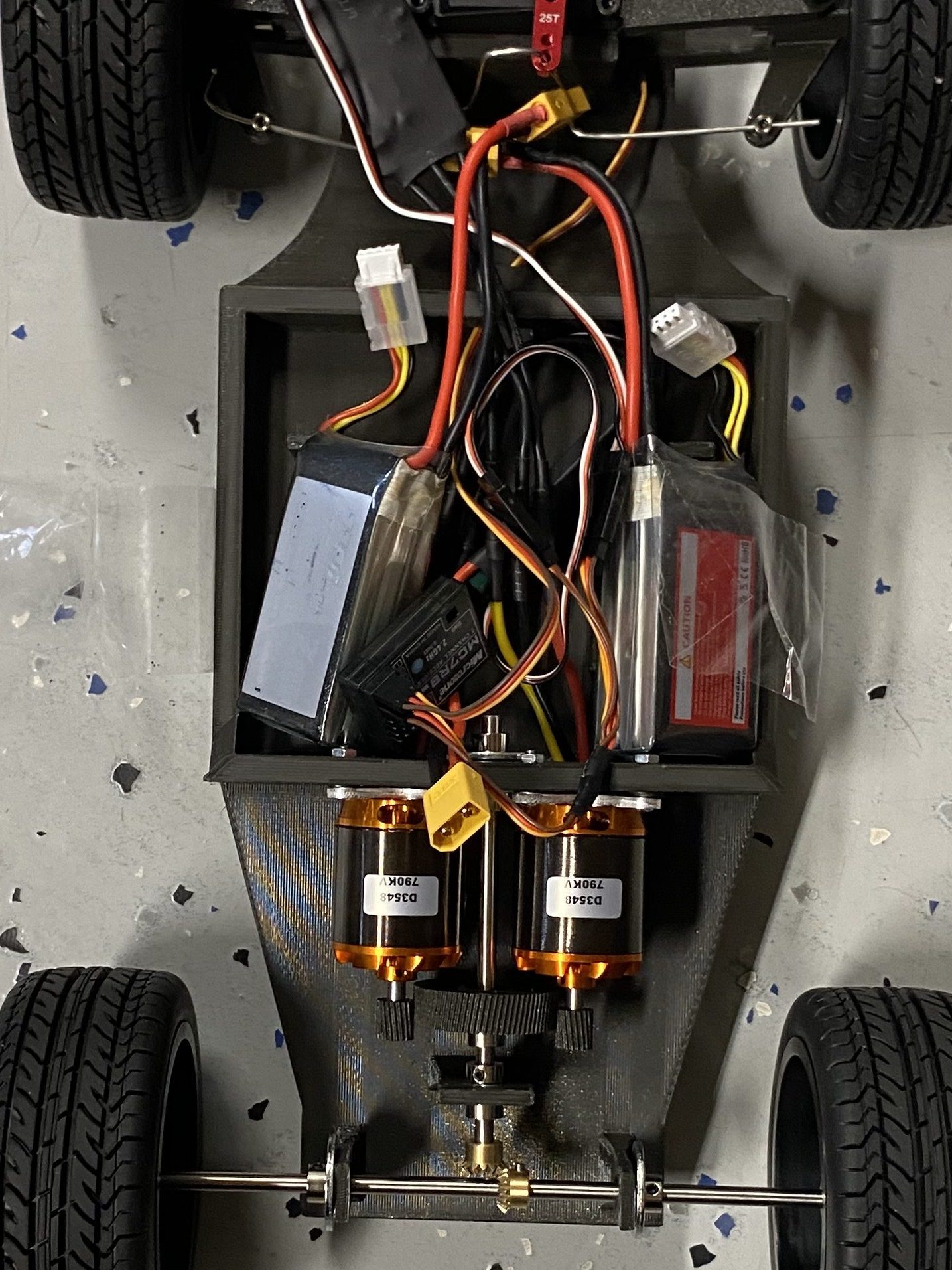
- This is the middle of the car and is used to store the electronic components in the car such as the 3S LiPo Batteries, the ESCs, and the receiver
- It has spaces on either side to allow the wires from the BLDC motors and the servo to enter from and helps contain the wiring to the middle only and helps achieve a clean aesthetic
- There are also stumps on the middle to keep the batteries in position and to decrease the amount of movement/sliding within the car
- Driving Section
- The rear side consists of two FLASH HOBBY D3548 790kv BLDC Motors that connect to a central gear with a gear ratio of 4:1 for torque
- This central gear connects to an axle that connects to the wheels’ axle via bevel gears.
- The bevel gears originally had a gear ratio of 1:1 but that proved insufficient so I increased the gear ratio to 25:15 or 5:3
- This gives us a total gear ratio of 20:3 or 6.67:1
Things that Worked
- Steering Knuckle/Servo System Design
- The usage of Pushrod Connector Linkages with the steering knuckles and servo was very efficient; it allowed the car to make sharp turns and high speeds with little to no problem.
- They also were rotationally free to spin, meaning that they could rotate to always face the servos even as the steering knuckles are being rotated.
- Gear Design
- The motor and central gears were printed very well and were able to withstand continuous use. I thought this would prove to be a problem due to the teeth of the gears being very small which would cause slipping and grinding of the gears but they ended up working very well.
- Low Center of Mass
- The Car was built to have a low center of mass, allowing it to be able to withstand tighter turns at faster speeds without tipping over.
- The way I designed it was to have all the heavier components (batteries, motors) underneath or at the same level as the wheel’s axle so it is almost like the car’s components are hanging underneath the wheels. This allows it to have a much lower center of mass which prevents it from being tipped over easily.
Improvements To Be Made
- ESC Overheating (first observed Nov 18, 2024)
- Over time, as you add more and more strain onto the motors or as you drive in harsher conditions, the ESCs tend to overheat due to the increase in current demand from the BLDC Motor which ends up being more than the ESC can handle
- This ends up overheating the ESC and even led to one of the MOSFETs of the ESC to “pop” due to a short between its terminals
- A MOSFET is essentially a transistor switch that is used in an ESC to control the power from the battery going into the motor. It does this by receiving PWM (pulse-modulation-width) signals which is from the yellow/white wire that comes out of the ESC.
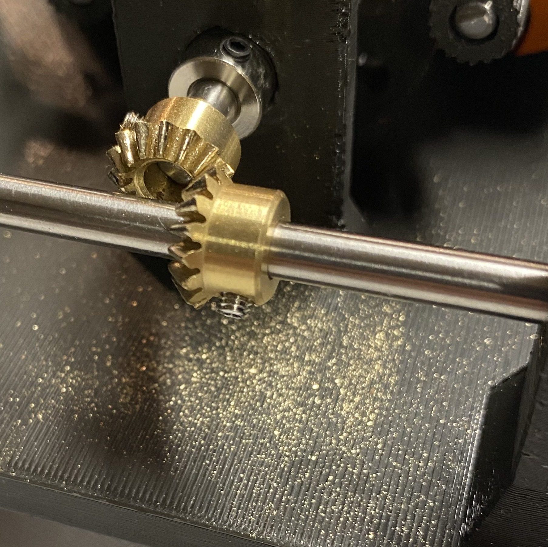
- Excessive Noise and Grinding of Gears (first observed Oct 29, 2024)
- This grinding is especially prevalent in the bevel gears in the back which transfer the motion of the axle directly powered by the motors to the perpendicular axle that connects to the wheels
- This is seen with the golden metal shavings under the gears
- This grinding is due to the motors not having enough torque (even with the 4:1 gear ratio) so it is much harder for the motors to accelerate the car from rest
- Overly Complicated/Messy Center Bin (first observed Oct 29, 2024)
- The center bin where the wiring, batteries, and ESCs are supposed to lie are extremely jumbled up and this creates a very messy and unaesthetic appearance
- This compacted bin also reduces the ventilation/airflow of the parts meaning that the ESC can overheat even more due to the clustering of the components
- ESC (first observed Nov 18, 2024)
- Over time, as you add more and more strain onto the motors or as you drive in harsher conditions, the ESCs tend to overheat due to the increase in current demand from the BLDC Motor which ends up being more than the ESC can handle.
- This ends up overheating the ESC and even led to one of the MOSFETs of the ESC to “pop” due to a short between its terminals
- A MOSFET is essentially a transistor switch that is used in an ESC to control the power from the battery going into the motor. It does this by receiving PWM (pulse-modulation-width) signals which is from the yellow/white wire that comes out of the ESC.
- The ESC is also a relatively cheap one (only 40A) and it was not designed for an RC Car application. This leads to it not being able to reverse which is something that an RC car should be able to do. We can fix this by swapping the ESC out for an RC-application ESC which usually have a much higher maximum current and are able to be programmed to move in reverse.
- Gear Ratio (first observed Nov 18, 2024)
- The current gear ratio is a 4:1 gear ratio but this still proves to have too little torque to accelerate the car; in the future, the gear ratio should be much greater (maybe a 8:1 or 10:1) in order to actually properly move the car.
- The current 4:1 gear ratio is the reason the car is overall insufficient, and also why there is unnecessary grinding in the gears.
- I fixed this problem by replacing the 15-tooth bevel gear on the wheels’ axle with a 25-tooth one
- This proved to be very effective and allowed a much better acceleration of the car from rest while still maintaining a relatively high top speed
- Steering Bracket (first observed Dec 3, 2024)
- The top steering bracket piece is taking on the front weight of the car as well as the shocks from any bumps encountered (due to there not being suspension in this version)
- This leads to that piece being under a lot of stress and it not being built to handle that.
- This problem can be fixed by redesigning that piece to be stronger, using a more flexible material that is impact-resistant (like TPU), or by adding suspension to those wheels.
- Heavy Frame (first observed Oct 29, 2024)
- After looking into SimScale for its FEA (Finite Element Analysis), I realized that my weight to stress resistance ratio was completely off for what I needed. I could have gotten away with using a much lighter infill to still get almost the same strength that I needed.
- This excessive weight added to the reason why my car was not moving at the expected speed.